Donn Stewart
13917 Deviar Dr
Centreville, VA 20120
dstew@cpuville.com
13917 Deviar Dr
Centreville, VA 20120
dstew@cpuville.com
Computer systems often use a bi-directional data bus to allow convenient connection of memory and other devices to the registers of the processor data path. A bus is a set of parallel wires. Bi-directional means that devices connected to the bus can either take input from the bus, or put output on the bus. In order for this to happen without outputs colliding, three-state buffers are used.
Recall that a computer consists of large networks of automatic switches, each of which is either on (logical 1, or 5V) or off (logical 0, or 0V). But remember, that in order to be either 5 or 0 volts, an output has to be connected, through the logic gate circuit, to either the 5V or 0V (ground) power supply leads of the gate. What would be the state of an output that was connected to neither? That is, pretend you cut the output wire, and it is hanging in the air.
For a logic circuit output to be useful, it must be able to switch between the two voltage states and pass current. That is, if an output is 5V, it needs to be able to pass some current to drive the inputs of the other gates to which it is connected. Similarly, if an output is 0V, it needs to be able to "sink" current, in order to operate the circuits it is tied to. The "cut wire" state is a third state, neither 1 nor 0, that is very useful in computer system design. The third state is also called "high impedance" because current will not be able to flow either into or out of an output that is in this state. The high impedance state can also be thought of as having a very high resistance. It is shortened to "Hi Z", because Z is a symbol for impedence, a general term for resistance to current flow in both DC circuits like those of a computer, and AC circuits like those of a radio. Here are simple switch diagrams of a two-state and a three-state device.
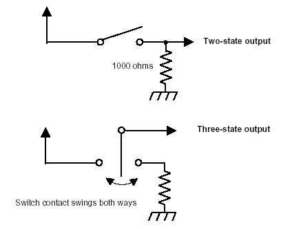
In the upper diagram, the switch can be open or closed. This type of switch is called a single-throw switch. If open, the output is connected through the resistor to ground, and will have a voltage of 0 with ability to sink some incoming current to ground through the resistor. When the switch is closed, the output will be 5V, with the ability to pass significant current to outside devices. The lower diagram shows a switch that can have three positions; closed to the 5V contact, open in the middle, or closed to the grounded contact. Such a switch is called a double-throw switch. Note that the circuit output is connected to the central pole of the switch. The middle position is the third state. It is just like a cut wire. The output, connected to the central pole of the switch, will not be able to conduct any current anywhere with the switch in the middle position and its voltage will be undefined. This is characteristic of the third, or high-impedance state.
Having a three-state logic device output allows us to take a huge short cut when we assemble a true computer system. It allows us to use a single set of parallel wires to pass data in two directions.
The bi-directional bus allows us to connect many separate devices that have three-state outputs to the same set of wires, and then use logic to select which devices will communicate to each other. The outputs of the other unselected devices will remain in the third state, and will be invisible to the active circuits. They will not interfere with the data communications between the active devices. We are bringing this up here, because computer memory is such a device, with three-state data outputs. When the memory write signal is given to a selected memory chip, the outputs behave as data inputs, in order to write data in the memory. When the memory write signal is inactive, the outputs behave as outputs, sending data onto the bus. When the chip is not selected, the outputs are in the third, high-impedance state, and the chip is invisible to other devices on the bus, such as input or output ports. It is convenient to think of the memory data lines as input/output lines, because they can change direction.
It is a simple matter to make a bi-directional bus using three-state logical devices. The two most commonly used are the three-state buffer, and three-state inverting buffer.
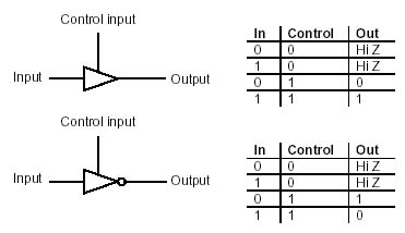
The control input is a signal that enables the gate to pass data when it is on (1). The control input is sometimes called an enable input. Here is how to make a bi-directional buffer out of two three-state buffers and an inverter.
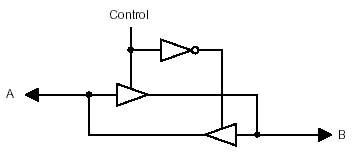
When control is 1, the data flows from A to B, and when it is 0, from B to A. In other words, when control is 1, A is the input and B is the output, and when control is 0, B is the input and A is the output. Thus A and B are input/outputs.
Inclusion of another control can allow the entire bi-directional buffer to go to the Hi Z state.
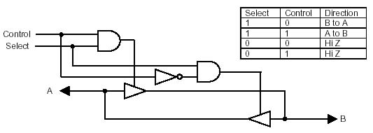
This type of circuit is used inside memory circuits to control the input/output lines.
In the data path of the homebuilt processor, we are faced with the problem of how to connect a register, with separate inputs and outputs, to a memory chip with bi-directional three-state input/outputs. First of all, the problem really only occurs during the memory write cycle, because otherwise the memory is either putting out data (if selected) or is in the high impedance state (if not selected). If the memory input/outputs are directly connected to register inputs, both of these conditions are tolerable. However, the register outputs cannot be connected directly to the memory input/outputs, because when the memory is in the output condition, you will have memory outputs connected to register outputs, which is not tolerable. We need to use a three-state buffer to prevent the register outputs from colliding with the memory outputs. The circuit is simple:
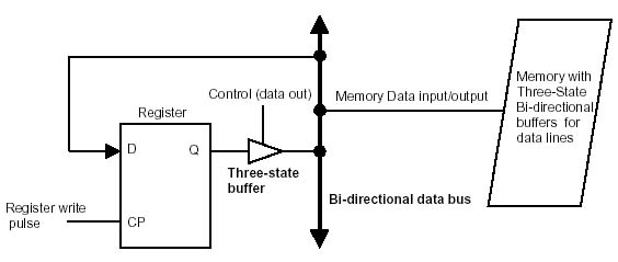
The three-state buffer protects the memory outputs from colliding with the register outputs when the memory is in the output mode. When the memory is in the input mode, the Data out control signal comes on, and the three-state buffer becomes an output.