13917 Deviar Dr
Centreville, VA 20120
dstew@cpuville.com


This project is a single board 8-bit computer that can be built with a few simple tools. It uses the Z80 processor, which is widely available and inexpensive. It was designed as a project for a high school computer class The design is taken largely from Steve Ciarcia's Build Your Own Z80 Computer, Byte Books/McGraw-Hill 1981. Recently, Google Books scanned this book and has it for viewing here. An additional source of ideas was Z-80 Microcomputer Design Projects by William Barden, Jr., Howard W. Sams & Co., Inc., 1980.
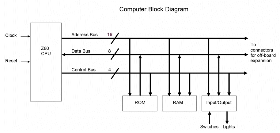
The design is very minimal, but expandable. The computer as shown here has 2K EPROM, 1K RAM, two 8-bit input ports, and two 8-bit output ports. The tiny ROM code shown in this site can be entered bit-by-bit into the EPROM with a simple programmer that the hobbyist can build. This ROM code allows program entry into RAM using the input ports, and the user can thus experiment with small programs. A useful expansion, not shown here, might be a serial port that can allow one to use a terminal program on a PC to enter code into the Z80 computer. Of course, one would have to write code to access the port.
The design has three different system clocks. The slow clocks (single step and 2 cycles per second), when used with a simple bus display, allow one to see the events taking place in the system. This is useful for debugging the hardware, and for seeing how the system performs its actions. The fast clock is a quartz crystal oscillator that drives the computer at its normal high speed of 1 MHz.
The computer block diagram is here. The schematics show decoding for several ports, although only two are actually on the board. The buses extend off the board by way of sockets on the right side. Additional boards can be connected to the main board using insulation displacement connectors (IDC's) and ribbon cables. The display board can be thought of as a system extension. Once the system is working, one could replace the display board with another board that has on it, say, a serial port, or a memory-mapped display.

Here is a list of the schematics. Astute visitor Randy L. pointed out that the picture of the computer has four LEDs in a header next to the switches that he could not find on the schematics. He is correct. These are indicators for the single step, slow clock, reset and final clock circuit outputs. I used inverters from the reset circuit 74LS04 to drive these LEDs. If you find any other mistakes, please let me know.
Clocks and ResetHere are wire-wrap lists. You really don't need these if you can follow the schematics, but they are useful for students who just want to get the thing done.
Wire-wrap list 1Here are the schematics for a simple EPROM programmer.
EPROM pulse circuitCode for the EPROM and some test programs for this project can be found on the Z80 code page.
Here are some notes on building and operating this computer.
This project was the prototype for a Z80 computer kit that I have for sale.