Donn Stewart
13917 Deviar Dr
Centreville, VA 20120
dstew@cpuville.com
13917 Deviar Dr
Centreville, VA 20120
dstew@cpuville.com
In another page I have shown you how to make a binary adder using AND-OR array logic. If you look at the AND plane diagram for the adder on that page, you will see that not every combination of inputs is accounted for:
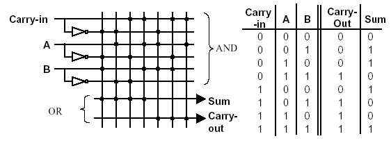
That is, there are eight possible combinations in the three-bit input, but only seven are decoded by the AND plane. That is because the AND-OR array only computes the cases when one or both outputs is a 1, and the case where both outputs is zero is not decoded. The AND plane of the adder is a partial decoder.
A full decoder is a very useful device in computer circuits. You can use it for the AND plane in your own logic circuits, and just leave unconnected the outputs you do not need. Here is an AND array diagram and truth table for a full one-of-eight decoder:
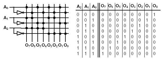
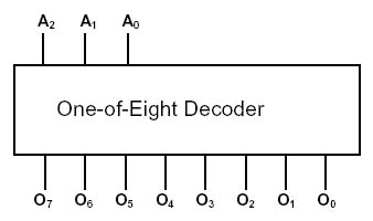
The decoder takes a three-bit binary number as input and turns on the corresponding output. An output is on only when its three-bit address is placed on the inputs. A decoder circuit diagram looks like this, using two-input AND gates:
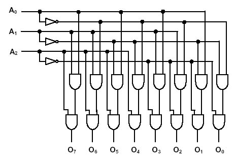
Like other circuits, the decoder can be symbolized by a simple rectangle with the name on it.
Like the logic gates, decoders of several types are available in the 74LS00 series. They are used in computers to decode addresses for memory, and as the AND plane for AND-OR arrays. You can make a read-only memory (ROM) from a decoder and multiple input OR gates. Memory ICs have large decoders inside them. A 2K memory needs a 10 to 2048 decoder (over 2000 outputs!). This is one reason why memory chips are slower than most other ICs in a computer system.
By using a decoder , AND gates and a multiple input OR gate, we can make data selectors, called multiplexors. Here is a four-input, one-bit multiplexor.
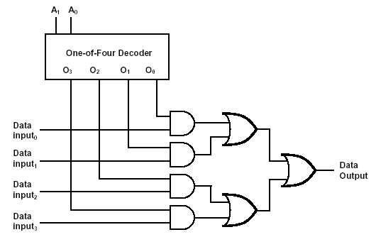
In this circuit, there are two address inputs and four data inputs. The circuit will pass the data input bit selected by the address input to the data output. The circuit can be thought of as a data selector, and the address inputs of a multiplexor are sometimes labeled as S1 and S2 for this reason. Multiplexors are used to make the data paths in a computer processor. For completeness, I will show you the de-multiplexor. While the multiplexor selects one of several inputs for one output, the demultiplexor selects one of several outputs for one input.
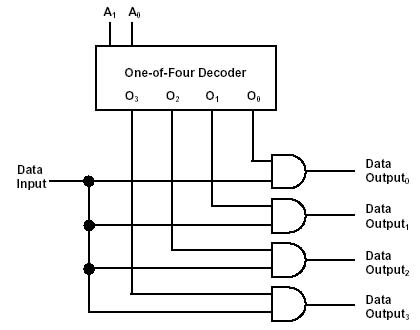
The demultiplexor is like a decoder with one extra input to determine whether the selected output will be a 1 or a 0. If the extra input is tied to 5V (made a 1 permanently), then the demultiplexor becomes a decoder. For this reason, the 7400 series of ICs has demultiplexor/decoders, and not separate demultiplexors and decoders.
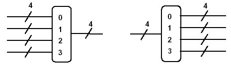
Multiplexors and demultiplexors can be symbolized the same way as the other logic circuits. We simply draw a box around the circuit. In this case, we use a symbol with rounded edges with numbers inside, indicating the inputs or outputs to be selected by the address inputs.
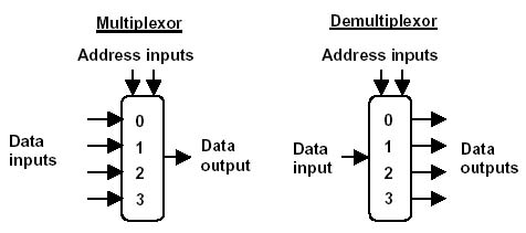
Data is assumed to flow from left to right. The address inputs need not be shown, since the number of inputs or outputs shows how many address bits are needed. Note the rounded corners on the symbol. This will be important later as we begin to build our computer diagram. The rounded corners and numbers inside distinguish the multiplexor/demultiplexor from the data register.
Again, multiplexors (and demultiplexors) can be grouped together in networks. This allows us to make multiple-bit data selectors. Data inside a computer is often represented as groups of bits. Four bits makes a nybble, for example, and can represent a number from zero to 15 decimal. By connecting together four multiplexors, we can make a four-bit data selector.
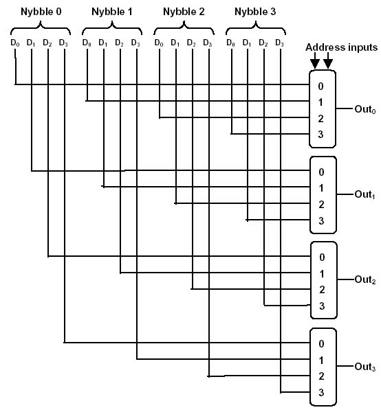
The four multiplexors shown above each have the same address inputs. The input nybble selected by the address input will appear on the outputs. To draw a multiple-bit multiplexor or demulitplexor we use the symbol for the one-bit variety with a number above the inputs or outputs to show that it is passing groups of bits.