Donn Stewart
13917 Deviar Dr
Centreville, VA 20120
dstew@cpuville.com
13917 Deviar Dr
Centreville, VA 20120
dstew@cpuville.com
I have made and sold Z80 computer systems with a serial port, so that you can do text input and output using a dumb terminal or a terminal emulation program on a PC. This is like the early PCs that were designed to work with CP/M, which was the operating system of choice for business applications.
However, many of the early 8-bit computers meant for home use had built-in keyboards and displays, or produced a composite video output so that a TV or simple video monitor could be used as the display, like the Apple II, TRS-80, and Commodore 64. These computers were designed with video game playing in mind, and had some form of a memory-mapped display to allow this. Many people have asked me if I could make a similar computer, which, because it is not dependent on a separate terminal for input and output, may be called a standalone computer. I started on a project to make a standalone computer about a year ago, and this page documents the results and what I have learned along the way.
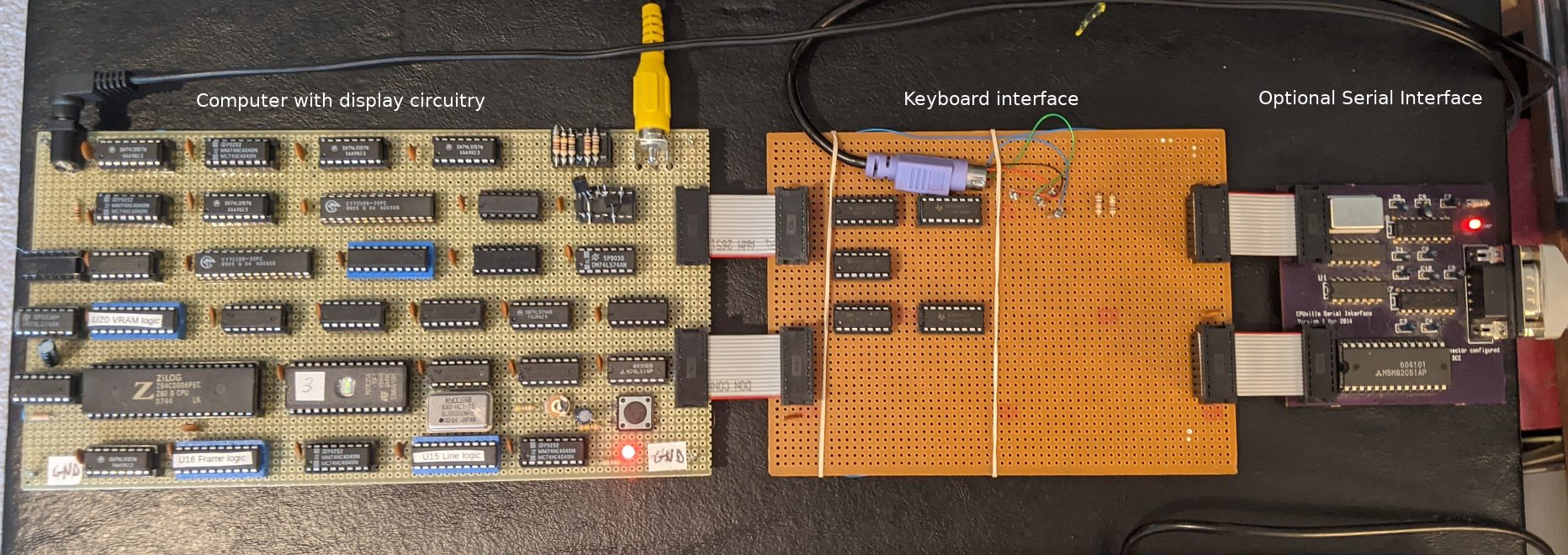
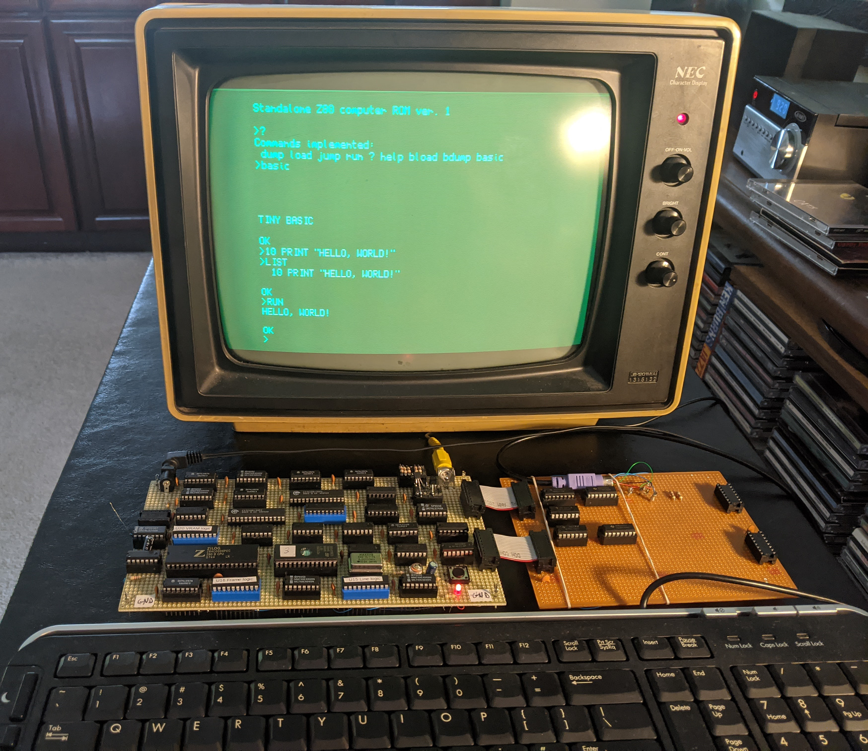
The standalone computer has a Z80 B processor overclocked to run at 8 MHz, which it handles fine. The memory space is divided into 8 kilobytes (KB) of ROM and 56 kilobytes of RAM. The RAM space includes 9600 bytes of video RAM (VRAM) from addresses 8000h to A580h. The entire RAM space is accessible to the processor. The ROM includes a system monitor similar to that used in the CPUville Single-board Z80 computer, with the exception that the commands for reading and writing the disk have been removed, and code to manage the video display and keyboard interface have been added. The computer produces composite black-and-white video output at 60 frames per second, with a resolution of 320 by 240 dots. The computer has a keyboard interface that accepts input from a PS-2 keyboard. The computer has connectors for an optional serial interface to allow loading programs from a PC. Schematic images of the computer system and the keyboard interface are here:
Standalone Z80 computer schematicThe most daunting challenge was making the video display. I was about to look on the internet to see how people have done this, but a friend (thanks, Paulo!) said I would learn more if did not copy anybody else's design and just came up with my own. So that is what I did. I started with a description of the composite video signal and worked backward to make a circuit that would produce the signal and display images stored in memory. If you look at my schematics and see things that I could have done a different way, feel free to let me know, but I think I got it mostly right.
There are limits on the resolution of a composite video signal. I decided to try for a 320 by 240 pixel resolution, in black and white, which is close to the upper limit of what these displays can produce. To get 320 dots on a line, given that a composite video line is drawn in about 53 microseconds, I needed a maximum dot time of about 53/320 = 0.165 microseconds, or a minimum dot frequency of 1/0.165 = 6.06 MHz. I used an 8 MHz oscillator for the video display and this worked well.
The composite video output signal voltage specification ranges between 0 and +3V, so I needed to make a circuit to produce the required voltage levels from the TTL signals produced by the video display logic. I used a voltage divider and some generic NPN transistors to produce the levels for a white dot, a black dot (blank), and a synch level. This worked well except the black dots were elongated to the right (the direction the electron beam in the display is traveling). Using the oscilloscope I could see that the video transistor was turning on sharply, but turning off slowly. I considered using a faster specialized transistor, but looking around I came across a simple fix to this problem called the Baker clamp:
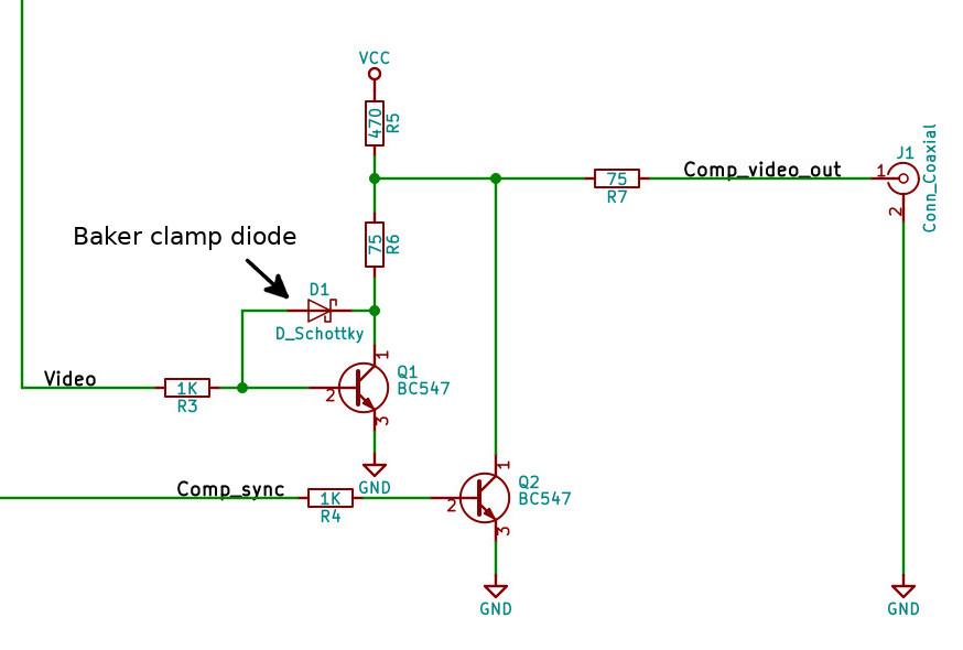
This is simple a Schottky diode (low forward voltage threshold) connected between the base and collector of the video transistor. This diode has the effect of taking some charge off of the base as the transistor comes on so that the base does not become heavily saturated. Then, when the transistor turns off, it has only a little charge to shed, and goes off quickly. This resulted in much better dot resolution. I did not need the Baker clamp for the synch level transistor, because this pulse is not really sensitive to a slightly slow transistor turn-off.
The digital signals required for the display are the synch pulses and the video signal itself (the dots). There are two synch pulses. The horizontal synch pulse is a 0V pulse that lasts 4.7 microseconds and is produced every 63.5 microseconds, for a line rate of 15.7 kHz. The vertical synch pulse is a 0V pulse that lasts 3 line-times and is produced every 16.6 milliseconds (for a frame rate of 60 per second). The video signal runs at a rate of 8 MHz, with each dot either on (white) or off (black).
I produce the synch signals by using counters. I feed the 8 MHz dot clock signal into the counters, and use logic to trigger flip-flops at certain dot counts corresponding to the times to start a pulse and stop a pulse. This works well. The counters are ordinary binary counters (not synchronous). The counter logic also resets the counters at the appropriate dot counts. The synch pulse counters also produce signals to turn the video display on and off at appropriate dot counts. Here is a summary of the signals produced by the line and frame logic circuits:
	     Line logic
Signal pulse		Pixel number, dec
HSYNC on		12
HSYNC off		49
RAM2 off bus		132
Display on		136
Display off		456
RAM2 on bus		460
Pixel Counter reset	508

	     Frame logic
Signal pulse		Line number, dec
RAM2 off bus		6
Display on		7
Display off		247
RAM2 on bus		248
VSYNC on		254
VSYNC off		257
Line counter reset	263
The video portion of the display circuit is an 8-bit shift register which takes bytes from the video display memory and produces a stream of bits that correspond to the bit pattern in the byte. The shift register is run using the 8 MHz oscillator as the shift clock. The shift register is "on" all the time. When the video display is on (when bytes are being fed to the shift register), the video memory was puts a byte into the shift register every 8 dot clock counts, and when the video display is off the shift register is putting out a stream of zeros.
The signal for the shift register to load bytes is a little complicated. The idea is to load a byte every 8 counts, and a small divide-by-8 logic circuit on the counter outputs produces this signal:
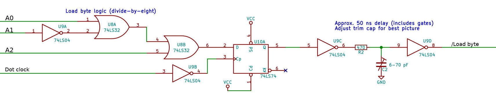
But there is a significant delay between when the VRAM address is incremented, and the new byte is displayed on the VRAM data outputs, so the divide- by-8 circuit produces the pulse a few counts after the three least-significant counter bits reach zero.
The timing of the shift register load pulse is critical. The new byte needs to be loaded into the shift register at exactly the right time, or else there will be a blurred image. This is because the shift register will immediately output the most-significant bit of the loaded byte, so if the byte is not loaded while the shift pulse is active, that dot will be missing from the output. I solved this by using an adjustable delay circuit. A trimmer capacitor in an R-C delay circuit can be adjusted so that the bytes are loaded right when a shift pulse is active. I used a test pattern with every other dot on (binary 0101 0101, or 55 hexadecimal) during adjustment.
Connecting the video display memory (video RAM, VRAM) was another complicated problem. The VRAM has to be connected to the system address and data buses when the CPU is placing data into it, but connected to the video display when putting dots onto the screen. When connected to the display, the VRAM gets its address from a byte counter, which is incremented every 8 dots and is reset when the end of the display frame is reached. A multiplexer selects an address from either the system address bus or the display byte counter, depending on a signal derived from the synch pulse outputs. Basically, the system will allow the CPU to put data into the VRAM only during the synch pulse intervals. During the time that the display is on, the system generates a WAIT input to the CPU if the CPU wants to read or write to an address in the VRAM range. The VRAM data bus is connected directly to the display shift register, and to the system data bus through a bi-directional buffer. The synch pulse signals control this data bus buffer so that it is open only during the synch pulse time, when the display is off.
One other small thing is a hardware interrupt from a slow (about 6 Hz) R-C oscillator circuit that is used to provide timing for the cursor blink and a power-on delay to allow the keyboard to intialize.
The keyboard interface hardware is pretty simple. I built a one-way interface (keyboard to CPU) to reduce hardware. This means that one cannot send commands to the keyboard to do things like turn on the caps lock LED or alter the key repeat frequency, but I think the trade-off acceptable for this project. The signal from a PS-2 keyboard is an 11-bit serial word, which has one start bit, 8 data bits, one parity bit, and one stop bit. I used two 8-bit serial-to-parallel shift registers in tandem to capture the 11 bits, polling bit 5 in the second register to see when the start bit arrived there. That would mean that the contraption had received the full 11-bit word. Then I could read each register, and extract the 8-bit data. This data byte is not a character code, but rather a keyboard scan code, which indicates which key has been pressed. The ROM software translates this scan code into an ASCII character code for display.
If a bitmap image is loaded into the video RAM the system will display that image on the screen. No software translation is needed. However, to display characters or video game sprites, rather extensive software is needed. The key routine is set_dot, which takes a pair of dot coordinates as input and sets the corresponding dot "on". There is also a clear_dot routine which turns dots off. These are the central drawing routines, and in order for the computer to be useful they had to do their jobs quickly. It became apparent that the best way to speed up these routines was to pre-compute offsets for the VRAM address of every byte and place these in a table, so that having the line and dot coordinates a simple lookup could be done one time for each dot to be set. This reduces the number of calculations needed to set or clear a dot. The amount of ROM and RAM devoted to the video display is increased by using tables in this way, but the trade-off was a good one I believe.
The character display system is designed with 24 lines of 52 characters, meaning each character occupies a box 10 dots high by 6 dots wide. I used the central 7 by 5 box of dots for most of the characters. This allows 2 lines for descenders on characters such as "g", and leaves one display line of space below a descender. It also allows one dot-width of space between the widest characters. A 7 by 5 box allowed for good symmetry of characters. The resulting font was easily readable (see the photos), but I am not entirely happy with it; the "r" seems a little squashed. But, it is easy to change, and I may continue to play with it.
Each character was drawn as one would draw a sprite, by going through a table of offsets for each dot of the character, given a starting display line and dot location for the character (the upper left corner dot). I could draw the characters quickly enough to keep up with my fastest typing speed, so I was happy with this.
The software for turning keyboard input into ASCII characters turned out to be surprisingly complex. Usually, a keypress generates one keycode, and in the unshifted state one can use a table to match that keycode with an ASCII character. However, the keyboard does not produce different keycodes when the shift key or control key is down, and does not keep track of shift lock. (Note that the caps lock LED on a PS-2 keyboard has to be turned on by sending a command to the keyboard. Simply pressing the caps lock key does not alter the keycodes that the keyboard sends.) These keys (shift, control, and caps lock) produce simple keycodes when pressed like all the other keys. But, the keyboard also sends a two-keycode sequence when any key is broken. By keeping track of making and breaking of the various keys the software can produce the proper ASCII characters, by using tables for unshifted and shifted characters.
Caps lock was a special problem. Like the shift key, the keyboard itself does not keep track of whether or not the caps lock is on. It is simple to keep track of the caps lock state in software (just toggle a caps_lock_down boolean variable with each press of the capslock key). But the behavior of the keyboard is significantly altered when the caps lock is on. That is, with caps lock on, a press of a number key should produce the numeral, which is what a regular unshifted keypress would produce. But, with the caps lock on, a press of an alphabetic key should produce the shifted character. And, with caps lock on, and with shift down, the press of a numeral key should produce the shifted character for that key, but a press of an alphabetic key should produce the unshifted character associated with that key. The final solution was to have four separate tables that associate a keycode with a character, for the four conditions of unshifted, shifted, caps lock unshifted, and caps lock shifted. So, more space in ROM was taken up.
Once I had good routines for displaying characters and for getting keyboard input I made a simple system monitor. The system monitor for the standalone Z80 computer is similar to, indeed derived from, the system monitor for the single- board Z80 computer. It gives a greeting message followed by a ">" prompt. The implemented commands can be seen by typing "?" or "help" at the monitor prompt. The monitor implements commands to dump hexadecimal memory contents to the display (dump), to directly alter memory from keyboard input (load), to load binary files into memory through and optional serial port (bload), to dump binary data from the memory to the serial port (bdump), and to run a program (jump or run). There is no disk interface in the hardware at present, so no disk commands are implemented. When I had finished all the software for the display, keyboard interface and monitor, this took up 6 kilobytes of space. I was using an 8K ROM IC, so this left about 2 KB of usused space. I put a variant of the integer BASIC interpreter Tiny BASIC in this space, and added a basic command to the monitor, so now the standalong Z80 computer can run BASIC from the ROM.
Tiny BASIC binary codeIn building this system I gained a lot of respect for those who built the "dumb terminals" used back in the 1970s and 1980s. Nothing "dumb" about those. Building a computer system is easier than building a terminal I think.
The system I built works well, but it is perhaps not ready for prime time (meaning making a kit from it). A kit would be rather expensive, since the PCB for it would need to be larger than those I have made before. And, there is essentially no software for it. It is possible that I could add a disk interface, like the one on the single-board computer, but getting the computer to run a disk operating system like CP/M would be a challenge. It is doable though. Overall the project was a real challenge and I learned a lot. If by studying these project pages you learn something too I am content with that.
--Donn Stewart, October 2020