Donn Stewart
13917 Deviar Dr
Centreville, VA 20120
dstew@cpuville.com
13917 Deviar Dr
Centreville, VA 20120
dstew@cpuville.com
The control logic is a finite state machine. A finite state machine is both a theoretical and actual device that uses sequential logic to perform a series of steps. The finite state machine has, like other logic circuits, an input and an output. In addition, it has a state, which is a number stored inside it. For computer control, the input is the current instruction and the current conditions (zero, minus or carry). The output is the bit pattern that controls the main board register write inputs and the main board multiplexors, which cause the instruction to be carried out. In addition to the control output, there is a next-state output that is fed back to the input of the finite state machine. At the clock edge, the next-state becomes the current state. The finite state machine used in my computer is a Moore machine, in which the outputs depend only on the current state. The next state, however, is determined by both the inputs and the current state.
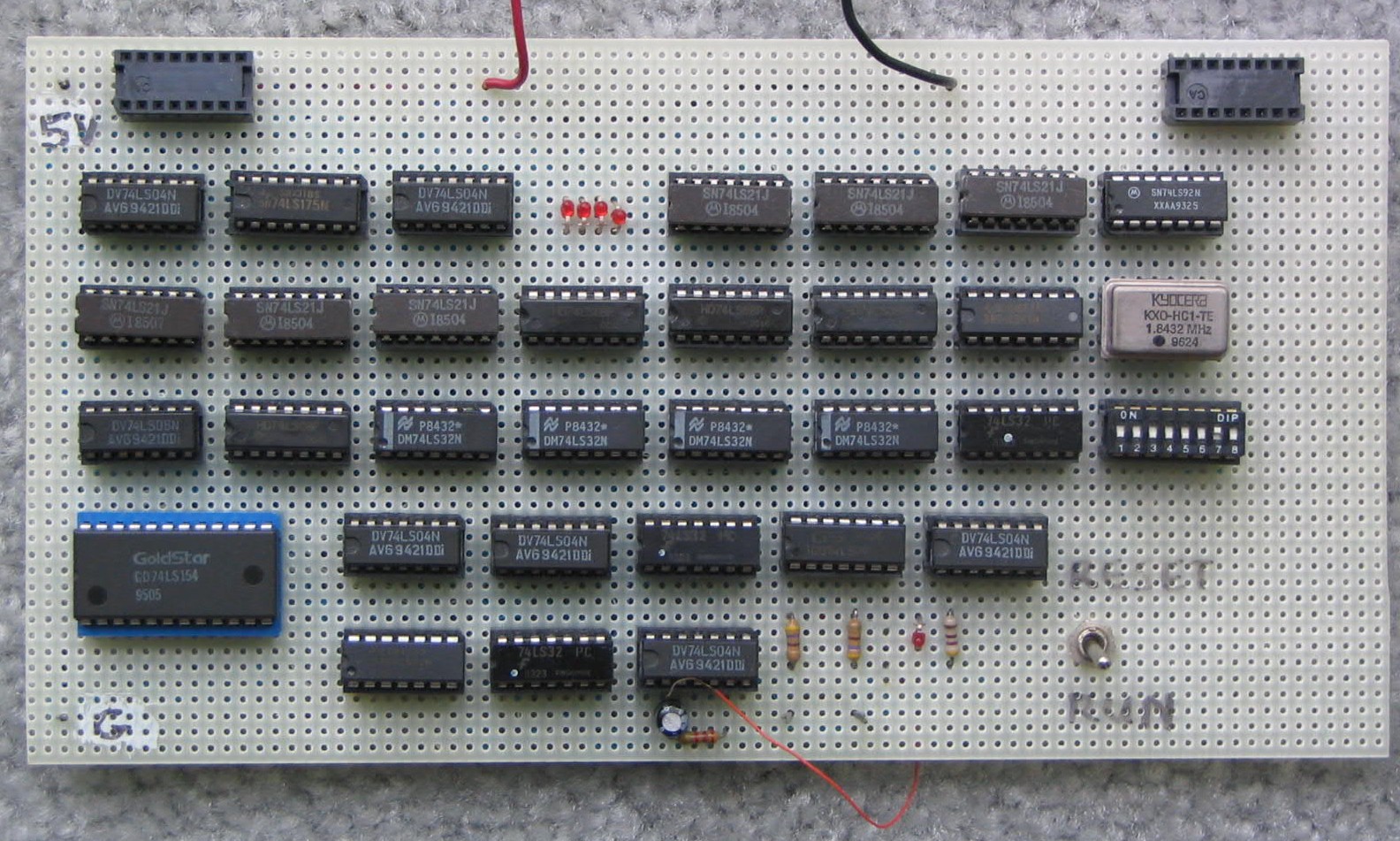
There are 11 states defined in the control logic for this computer processor. The finite state machine logic is made of a 4-bit state register and an AND-OR array. There are no large-scale integrated circuits used. The large chip at the lower left is a 4 to 16 decoder. The current state is displayed on the four LEDs near the top of the board. The states are defined as follows:
| State | Action Performed | Operations that use the state |
|---|---|---|
| 0 | Instruction fetch/Program counter increment | All |
| 1 | Instruction interpretation | All |
| 2 | Data fetch | Arithmetic/logical operations |
| 3 | Arithmetic instruction, includes carry write | ADD, SUB, ADC, SBC |
| 4 | Logic instruction, no carry write | AND, OR, XOR, NOT |
| 5 | Load accumulator immediate (value in current instruction) | LDI |
| 6 | Load accumulator from memory | LDM |
| 7 | Store accumulator to memory, first step | STM |
| 8 | Store accumulator to memory, second step | STM |
| 9 | Jump immediate (target address in current instruction) | JMP, and conditional jumps when condition true |
| 10 | Jump indirect (target address in memory) | JPI |
Instructions are carried out by cycling through a series of states in the correct order. For example, the ADD instruction in carried out by running through states 0, 1, 2 and 3. Here are the states for each instruction:
| Hex Opcode | Instruction Mnemonic | States |
|---|---|---|
| 0 | ADD | 0, 1, 2, 3 |
| 1 | ADC | 0, 1, 2, 3 |
| 2 | SUB | 0, 1, 2, 3 |
| 3 | SBC | 0, 1, 2, 3 |
| 4 | AND | 0, 1, 2, 4 |
| 5 | OR | 0, 1, 2, 4 |
| 6 | XOR | 0, 1, 2, 4 |
| 7 | NOT | 0, 1, 4 |
| 8 | LDI | 0, 1, 5 |
| 9 | LDM | 0, 1, 6 |
| A | STM | 0, 1, 7, 8 |
| B | JMP | 0, 1, 9 |
| C | JPI | 0, 1, 10 |
| D | JPZ, condition met | 0, 1, 9 |
| D | JPZ, condition not met | 0, 1 |
| E | JPM, condition met | 0, 1, 9 |
| E | JPM, condition not met | 0, 1 |
| F | JPC, condition met | 0, 1, 9 |
| F | JPC, condition not met | 0, 1 |
The correct arithmetic/logical operation is performed by the ALU, because it reads the lower 3 bits of the opcode directly. At the end of each series of states, the next state is 0, causing a new instruction to be fetched. Each state takes exactly one clock cycle, so the longest instructions are 4 clock cycles long. Thus, at a clock speed of 1 MHz, the computer can perform 250,000 arithmetic instructions per second. The control logic was thoroughly tested after construction using the test board.
The control board also has the reset and clock circuits. Reset is performed by forcing the program counter and state registers to zero. When the reset is released, the computer will fetch the instruction in memory location 000h and start from there. There are three clocks. The crystal is the fast clock; a 1.8 MHz clock is currently in place. A slow 2 Hz clock (2 cycles per second) is made from an R-C oscillator. This slow clock allows debugging of the computer hardware. A single-step clock is also present. The wire protruding from under the lower edge of the board is used to ground two contacts seen nearby, causing a flip-flop to change states. An LED shows the state of the clock line. The DIP switches select the clock being used.
Links to Original CPU pages: