Donn Stewart
13917 Deviar Dr
Centreville, VA 20120
dstew@cpuville.com
13917 Deviar Dr
Centreville, VA 20120
dstew@cpuville.com
In the overall design page, I showed a diagram of the 8-bit computer, and called it the "data path". That data path diagram included the memory and the ALU. However, to build the processor, it would be best to divide the electronics into a few separate boards. For example, the memory and input-output ports, which include disk drives or serial interface devices, would be on a separate board or boards, which I will call the "system". For the system, I used the CPUVille Z80 computer kit boards. The 8-bit processor would connect to the Z80 computer system through a system connector, adapted to plug into the Z80 socket on the system main computer board, as shown on the demo video on the 8-bit processor index page. The ALU would also be on a separate board. Thus the processor would be left with a data path board that had the three registers (the program counter, instruction register, and accumulator) and the various multiplexors that guide the data to appropriate targets. Here is a diagram of the processor, showing the data path without the ALU and memory:
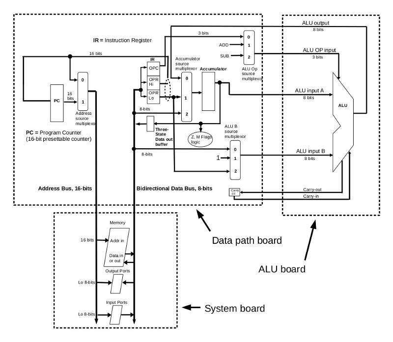
Looking at this diagram, it is clear there need to be connectors to pass signals between the data path, and the system and ALU. Not shown is another connector to a board that will display the contents of the three registers on the data path board. Also not shown is a connector between the data path board and the control logic board. This will be discussed on the control logic design page.
8-bit processor links: